Modeling the System Architecture
Each computer-based system can be modeling as information transforms using an input to processing to output architecture. Pirbhai and Hatley (HAT87) have extensive this view to include 2 additional system features-user interface maintenance and processing self-test processing. While these additional types are not present for every computer-based system they are very usual and their specification makes any system model more robust. By using a representation of input- processing- output user interface processing and self-test processing a system engineer can create a model of system components that sets a foundation for final needs design and analysis steps in every of the engineering disciplines.
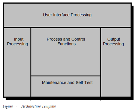
To build the system model an architecture template [HAT87] is used. The system engineer allocates system parts to each of 5 processing regions within the pattern (1) user interface (2) input (3) control and system function (4) output and (5) self-test and maintenance. The format of the architecture pattern is described in fig 14.2.
Such as nearly all modeling methods used in software engineering and system the architecture pattern enables the analyst to build a hierarchy of detail. (ACD) which is also known as architecture context diagram resides at the top stage of the hierarchy.

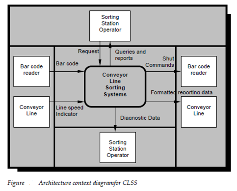
The context diagram builds the information limits among the system being implemented and the environment in that the system is to operate [HAT87]. Which is the ACD describe all external producers of information used through the system all external consumers of information established through the system and all entities which communicate by the perform maintenance or interface and self-test. To define the use of the ACD let consider a comprehensive edition of the conveyor line sorting system (CLSS) that is discussed earlier in this. The extended edition makes use of PC at the sorting station site. The Personal Computer executes all CLSS software interfaces with the bar code reader to read component number on each box interfaces with the conveyor line monitoring equipment to obtain conveyor line speed and stores all element number sorted interacts with a sorting station operator to produce a variety of diagnostics and reports sends control signals to the shutting hardware to sort the boxes and communicates with a middle factory mainframe automation. The ACD for CLSS is described in figure 14.3.
Every box which is shown in figure represents an external entity which is a consumer or producer of information from the system. Example for the barcode reader produces information which is input to the CLSS system. This symbol for the entire system or major subsystems, at lower levels is a rectangle with rounded corners. Therefore CLSS is represented in the ACD represent data and control as it moves from the external environment into the CLSS system. External entity bar code reader gives input information which is labelled bar code. In fact, the ACD places the context of its external environment into any system.

System engineer refines the architecture context diagram through considering the shaded rectangle in described figure 14.3 in more detail. The major subsystems which enable the conveyor line sorting system to function within the context describe through the identified ACD. In the above figure 14.4 the major subsystems are described in an architecture flow diagram (AFD) which is derived from the ACD. The Information flow across the regions of the ACD is used to teach the system engineer in establishment the AFD a more detailed schematic for CLSS. The architecture flow diagram shows major subsystems and important lines of data and control flow. In fact, the architecture patterns partitions the subsystem processing into each of the 5 processing regions discussed previously. At this level each of the subsystems can contain 1 or more system parts example for software, hardware, and people as due through the system engineer.
Initial architecture flow diagram becomes the top node of a hierarchy of AFDs. Every rounded rectangle in the real AFD can be expanded into another architecture pattern dedicated solely to it.
This procedure is described in systematic manner in the figure which is given below. Every AFD for the system can be used as a beginning point for subsequent engineering steps for the sub system which has been defined.
Subsystems and the information which flows among them can be particular bounded for subsequent work of engineering. The narrative elaboration of every subsystem and a definition of all information which flow among subsystems become important part of the system specification.