Route Sheet or Operation Sheet
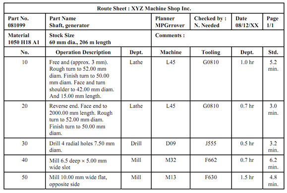
Route sheet or operation sheet describes the processing sequence for individual parts just like engineering drawings are utilized to specify the product design. Engineering drawings are used for product design where as route sheets are used for manufacturing. A route sheet comprises the following information :
1. The component, its name and drawing.
2. Information regarding all operations to be performed on the workpart, listed in the order in which they should be performed.
3. A brief description of each operation indicating the processing to be accomplished, along references to dimensions and tolerances on the part drawing.
4. The particular machines on which the work is to be done.
5. Any special tooling, like dies moulds, cutting tools, jigs or fixtures, and gauges.
Apart from these some companies also include cycle time standards, setup times and other data. It is also called a route sheet because the processing sequence defines the route that the part must follow in the factory. Figure 2 below illustrates a typical route sheet.
Typical guidelines in preparing a route sheet are given below :
- Operation numbers for consecutive processing steps must be listed as 10, 20, 30, etc. This permits new operations to be inserted if necessary.
- A new operation and number must be fixed while a workpart leaves one workstation and it is transferred to another station.
- A new operation and number should be specified if a part is transffered to another workholder (for example. jig or fixture), even if it is on the same machine tool.
- A new operation and number must be fixed if the workpart is transferred from one worker to another, like on a production line.

Figure 2 : Route Sheet