Graphical Design Notation
A picture is worth a 1000 words but it's rather important to recognize which picture and which thousand words. There is no question which graphical tools like as the flowchart or box diagram give excellent pictorial patterns which readily depict procedural detail. While, if graphical tools are misused the wrong picture may lead to the wrong software.
The flowchart was once the most broadly used graphical representation for procedural design. Uncertainly it was the broadest abused technique as well.
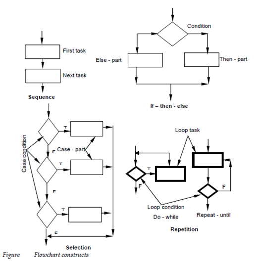
The flowchart is quite easy pictorially. The box is used to indicate a processing step. The diamond present a logical arrows and condition show the flow of control. In the Figure 22.4 describe the 3 structured constructs. The Sequence is represented as 2 processing boxes connected through a line of control. The Condition also called if-then-else is depicted as a decision diamond that if false invokes else-part processing or if true causes then part processing to occur. Repetition is represented using 2 slightly various forms. The do-while tests a condition and executes a loop task repetitively as long as the condition holds true. The repeat-until executes the look task 1st then tests a condition and repeats the task until the condition fails. The collection construct describe in the figure is really an extension of the if-then- else. The parameter is tested through successive decisions until a true condition happens and a case part processing path is executed.
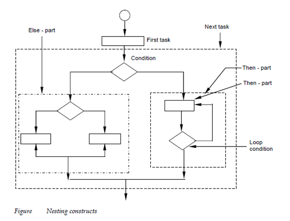
Structured constructs may be nested within one another as describe in Figure 22.5. In the figure a repeat-until forms the then part of an if-then else describe enclosed through the outer dashed boundary. Another if-then-else forms the else-part of the major condition. At Last, the condition itself becomes a 2nd block in a sequence. Through nesting constructs in this manner a complex logical schema may be established. It should be noted which any one of the blocks in the Figure 22.5 could reference another module thereby accomplishing procedural layering implied through program structure.
In common the dogmatic use of only the structured constructs can begin inefficiency when an escape from a group of nested conditions or nested loops is needed. More important while complication of all logical tests along the path of escape can cloud software control flow rise the possibility of error and have negatives impact on maintainability, readability. So the question is what can we do?
The designers left with 2 options that are:
(1) The procedural representation is redesigned so which the escape branch is not needed at a nested location in the flow of control or (2) the structured constructs are violated in a controlled manner ; that is a constrained branch out of the nested flow is designed. Option one is obviously the ideal approach but option can be accommodated without violating of the spirit of structured programming.
One other graphical design tool the box diagram evolved from a desire to establish a procedural design representation which would not allow violation of the structured constructs. Established through Shneiderman and Nassi and complete through Chapin the diagrams also called Nassi-Shneiderman charts, N-S charts or Chapin charts have the following characteristics:
(1) functional domain that is the scope of repetition or an if-then-else is well described and clearly visible as a pictorial representation;
(2) arbitrary transfer of control is impossible;
(3) the scope of local and\or worldwide data can be simply determined
(4) recursion is easy to represent.
The diagram representation of structured constructs using the box graphic is described in Figure . The fundamental parts of the diagram are a box. To represent sequence 2 boxes are associated bottom to top. To represent an if-then-else a condition box is followed through a then-part box and else-part box. The Repetition is depicted with a bounding pattern which encloses the procedure to be repeated. At last selections represented using the graphical form describe at the bottom right of the figure.
Such diagram a box flowchart is layered on multiple pages processing parts of a module is refined. A call to a subordinate module can be represented through a box with the module name enclosed through an oval