State Of Stress in Combined Bending and Shear:
So far we have been analysing the state of stress defined by stress components σx, σy and τxy. But we have not directed our attention as to how various stress components is induced and how they vary within the solid body and also how to recognize the critical locations. In this and the further, we shall consider two specific types of loading and identify the pattern of stresses induced in these cases.
You would have seen a huge number of girders supporting bridges and still a large number of beams supporting roof or floor slabs in buildings. Here you will learn how these members are loaded and supported and how the stresses induced in them are computed. Here we shall consider a few simple cases.
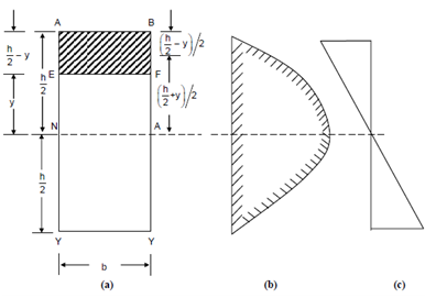
Consider a beam of rectangular cross-section as shown in Figure. On any section of the beam there might be acting two kinds of reactive resistance, namely, a Bending Moment M and a Shearing Force Q. In words of the cross-sectional dimensions (breadth 'b' and height 'h') the stress elements on a layer located at a height 'y' from the neutral axis (centroidal axis here) are provided as follows:
(i) σx = - 12My/bd3
(ii) σ y = 0
(iii) τxy = 1.5Q/bh (1-4y2/h2)
The differentiation of stresses across the depth as per Eqs. (i) and (iii) are display in Figures (b) and (c). (How Eqs. (i) to (iii) are acquired and how to get corresponding expressions for breams or girders of other cross-sections will be dealt with in detail in further).
