Programming Examples of Preparatory Functions
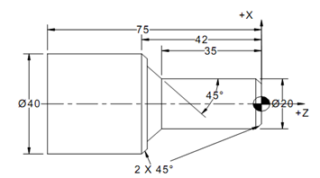
For the components shown below (AISI 1045 steel) make a part program for machining on the CNC turning centre.

Figure 37: Example for Program Writing
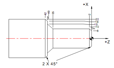
In this example we are assuming that the program is being written only to machine the final contour and that the initial part has already been cleared by the roughing cuts. In order to write the program, we need to get the points on the contour as per the coordinate system chosen for the component. The datum for the part is taken as the end point of the part as shown in Figure 37. The calculated coordinate points are shown in Figure 38. In this, we are assuming that the tool is sharp without any tool nose radius. In the next example, we will take the effect of nose radius and see how the coordinates change.

Figure 38: Coordinate Points of the Contour
The program is written below with some comments. The program is shown completely in absolute mode programming.
N04 G71; START OF FILE Metric units
N08 G0 X25.0; Go to initial position
N12 Z65.0;
N16 M06 T1; Tool change T1 Profiling Tool
N20 S2000 M03; SPINDLE ON N24 G0X10.0 Z2.0000;
N28 G1 X8.0 F120.0;
N32 X10.0 Z-2.0;
N36 X10.0 Z-35.0;
N40 X15.0 Z-40.0;
N44 X18.0 Z-40.0;
N48 X20.0 Z-42.0;
N52 X22.0 Z-42.0;
N56 G0 Z50.0;
N60 M05;SHUT OFF SPINDLE
N64 M02;END OF FILE