Bridge rectifier:
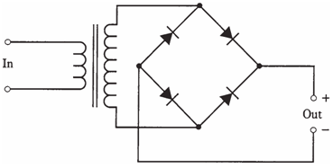
The other way to get full wave rectification is bridge rectifier. The diagram of it is shown in the figure given below. The output waveform is like that of full wave, center tap circuit.
The average direct current output voltage in bridge circuit is 90 % of the RMS alternating current input voltage, similar to the case with center tap rectification. The PIV across diodes is 1.4 times RMS alternating current input voltage. Thus, each diode requires having a PIV rating of at least 2.1 times the RMS alternating current input voltage.

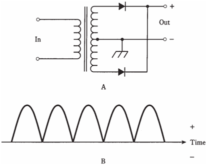
Figure-- At point A, schematic diagram of a full-wave, center-tap rectifier. At point B, output waveform from this rectifier.

Figure -- Schematic diagram of a full-wave bridge rectifier.
The bridge circuit does not require a center tapped transformer secondary. This is its basic practical advantage. Electrically, bridge circuit uses entire secondary on both halves of the wave cycle; the center-tap circuit uses one side of the secondary for one half of the cycle, and the other side for the other 1/2 of the cycle. For this very reason, the bridge circuit makes more efficient use of transformer.
The basic disadvantage of bridge circuit is that it needs 4 diodes rather than 2. This does not always amount to much in the terms of cost, but it is important when a power supply should deliver a high current. Then, the extra diodes -2 for each half of the cycle, instead of one-dissipate more overall heat energy. When current is used up as heat, it cannot go to the load. Thus, center tap circuits are preferable in the high current applications.