Potential Measurement with Potentiometer:
Schematic diagram of a simple poetntiometer is given in Figure. To understand the functioning of the instrument it can be divided into two parts: a voltage divider and the galvanic cell part.
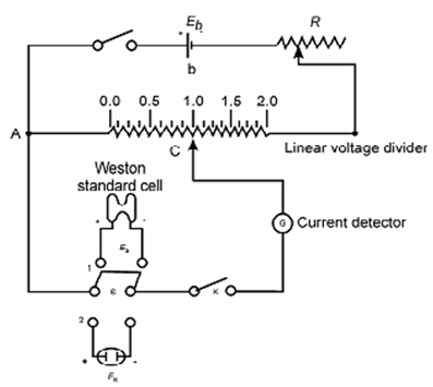
Figure: Circuit diagram for a laboratory potentiometer
The working battery with potential Eb is connected to the terminals of a linear voltage divider AB. The electrical resistance, RAC, from one end A to any point C, is directly proportional to the length AC of the resistor that is RAC µ AC or RAC = kAC, where k is a proportionality constant. Within its easiest form the divider consists of a uniform resistance wire mounted on a meter stick. A sliding contact permits variation of the distance A and C and therefore the output voltage. The Divider is precision wire-wound resistor formed in a helical coil. Involved also is a sensitive current-detecting device G, which may be either a sensitive galvanometer or a dc amplifier, a tapping key, K, by which the circuit can be momentarily closed, and a double pole and double throw switch S to permit insertion of the unknown cell with potential, Ex or standard cell of known potential ES into the circuit. A potential of working battery, Eb, is greater than that of Ex or of ES.