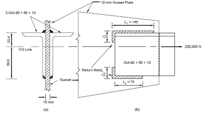
Design the welded connection:
Two ISA 90 × 60 × 10 angles form a tie member of a truss and is subjected to an axial pull of 200 kN. They are linked to both sides of a 10 mm gusset plate as display in Figure. Design the welded connection.
Solution

Figure
Maximum size of the fillet weld = 3/4 × toe thickness of angle
= 3/4 × 10 = 7.5 mm.
Assuming 6 mm size fillet welds on both sides of gusset plate to each angle axial force in each angle = 200000/2 = 100000 N which is assumed to act through the CG line of the angle. There are two runs of fillet welds of length L1 and L2 are applied to each angle one at the top edge corner and the other at the bottom tip of the leg as shown in Figure 17.
Throat thickness of weld = 0.7 × Size of weld = 0.7 × 6 = 4.2 mm
Permissible shear stress in weld = 110 N/mm2
∴ Strength of weld per mm length = 110 × 4.2 = 462 N.
Taking moment of forces about the bottom weld line (L2), we should have
462 × L1 × 90 = 100000 × 59.6;
giving L1 = (100000 × 59.6 /462 × 90) = 144 mm.
Similarly, taking moments about the top weld line (L1)
462 × L2 × 90 = 100000 × 30.4;
giving L2 =(100000 × 30.4/462 × 90) = 74 mm .
∴ Gives 145 mm long weld at top corner and 75 mm at bottom tip with return welds of length 2 × 6 = 12 mm each as shown in Figure.