Cutter Radius Compensation
It has been seen in the previous examples that though the hole making operations are relatively easy with very little coordinate calculations, the contouring programs do require the ability to offset the given part contour for the purpose of developing the program. The programmed contour depends upon the size of the cutter chosen. However, in case when the programmed tool is not available for whatever reason, and if that needs to be substituted by a different cutter, then the program needs to be rewritten with all the associated calculations. Further, it was also noted that the actual part program requires complex calculations as was seen in the previous examples. The problems become more complicated as the geometry becomes complex.

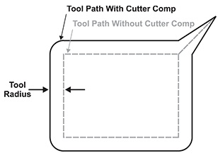
Figure 19 : Cutter Radius Compensation
This can be helped by writing programs assuming a tool of zero radius so that the programmed contour and the actual part contour coincide. The actual diameter of the tool can be entered into the controller at the time of running of the component such that the controller compensates for the radius of the tool. This is generally termed as cutter diameter compensation, though the actual compensation will be the radius. The following codes are used for the purpose:
*G40 Cutter compensation, cancel
G41 Cutter radius compensation left
G42 Cutter radius compensation right
These are modal and the one programmed in any block remains active till cancelled by the cancel command G40. Left compensation should be first cancelled before the right compensation is started. Same is the case with the right compensation.
The right or left for the compensation is established when looking in the direction of the tool movement for cutting. During the operation with cutter compensation on, the control automatically calculates the tool path as offset in the correct direction. However, during the startup and cancelling of the compensation the actual position is dependent upon the next or previous move respectively.