Canned Cycles
The reader might have noticed that the turning programs become unnecessarily long because of the large number of cuts needs to be taken. This bulk in the program can be eliminated by the use of canned cycles similar again to that of the machining centre programming. However, the type of canned cycles in turning centres are not standardised by the ISO and, therefore, will be different in different controls. The typical motions of Fanuc controls are given below while the other controls have similar cycles, but may be using different codes.
Turning Canned Cycle, G90
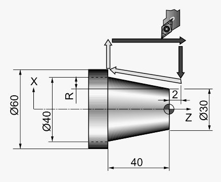
A typical rough turning canned cycle is shown in Figure 5.57. The tool is to be positioned at a position to the right hand top corner with sufficient clearance in the X and Z directions as shown in Figure 5.57. The program then specifies the opposite corner that requires a rectangular cut using the X and Z coordinates. Then the canned cycle generates the following motions:
Move rapid to the X-coordinate specified to take the depth of cut.
Move at feed rate (cutting metal) to the Z-coordinate specified.
Retract at feed rate to the initial X position.
Retract rapid to the start point.

Figure 57: Rough Turning Canned Cycle (G90) Operation
Facing Canned Cycle, G94
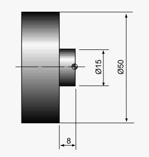
A canned cycle very similar to the rough turning cycle described above is the face cutting cycle G94. The operation of this cycle is very similar except the order of motions are reversed, i.e. position along Z-axis and then do cutting along X-axis as shown in
Figure 58 this can also be used for tapered surfaces by using the K word address to specify the taper. The actual usage is as follows:
The actual motions performed are as follows:
Move rapid to the Z-coordinate specified to take the depth of cut.
Move at feed rate (cutting metal) to the X-coordinate specified.
Retract at feed rate to the initial Z position.
Retract rapid to the start point.

Figure 58 : Face Cutting Canned Cycle Operation
Thread Cutting Canned Cycle G92
Operationally the thread cutting cycle is similar to the rough cutting cycle G90, which was described earlier. The additional information provided in this cycle is the synchronisation of spindle motion and the feed motion (G33) during the longitudinal feeding motion for the purpose of thread following.