Audio oscillators
The audio oscillators find uses in ambulance sirens, doorbells, electronic games, and those little toys which play simple musical tunes. All the AF oscillators work in same manner, consisting of amplifiers having positive feedback.
A simple audio oscillator
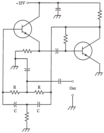
One form of AF oscillator which is popular for general purpose use is twin-T oscillator. The frequency can be determined by values of resistors R and capacitors C. The output is a nearly perfect sine wave. The small amount of distortion helps to alleviate irritation produced by a pure sinusoid. This circuit uses 2 NPN bipolar transistors. Two JFETs could also be used, which is biased for class-A amplifier operation.
The multivibrator
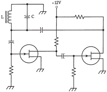
Another audio-oscillator circuit makes use of two identical common-emitter or common-source amplifier circuits, joined so that the signal goes around between them.

Figure-- A twin-T audio oscillator.
This is at times called as multivibrator circuit, although this is technically a misnomer, the term is more suitable for various digital signal generating circuits.
The two N-channel JFETs are connected to form the oscillator as shown in the figure given below. Each stage amplifies signal in class-A, and reverses phase by 180 °. Thus, the signal goes through a 360-°shift each time it gets back to any particular point. A 360-°shift results in the positive feedback, is effectively equivalent to no phase shift.
The frequency is set by an LC circuit. The coil uses a ferromagnetic core, as stability is not of great concern and as such a core is required to obtain the large inductance required for resonance at audio frequencies. The value of L is from 10 mH to as much as 1 H. The capacitance is chosen according to formula for the resonant circuits, to obtain an audio tone at frequency required.

Figure--A “multivibrator” type audio oscillator.