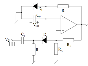
Monostable Multivibrator using an Op-amp:
As shown C1 R1 and D2 constitute a pulse shaping circuit. A monostable circuit, as the name implies, contain a permanent stable state. It may be easily deduced that this permanent stable state is V0 = Vsat = HIGH (with D1 clamped at 0.6 V, if β is sufficient to make + β Vsat > 0.6, the circuit would be in V0 = + Vsat = HIGH state. Even if the circuit accidentally begin from V0 = - Vsat, signal at non-inverting input is - β Vsat and capacitor C0 charges until voltage across it becomes more negative than - β Vsat at which time V0 switches to + Vsat and would remain so for all times to come until forced to modify by applying an external trigger.
Upon the application of an external signal (Ve) resulting in a short (narrow) negative going trigger pulse (Vtr) at t = 0, the V0 goes LOW. Vco changes exponentially towards - Vsat and when Vco attain more negative than - β Vsat, output becomes HIGH. The time- period during which waveform remains LOW (- Vsat) may be followed to be time taken by C0 to change from 0.6 volts to β Vsat and may be calculated from
Vco (t ) = A + B e (- t / T1)
Considering that with t = 0, Vco (0) = 0.6 and for t = ∞ , Vco ( ∞ ) = - Vsat, one may find
that
Vco (t ) =- Vsat + (Vsat + 0.6) e( - t /T1)
For t = T, Vco = - β Vsat. Therefore, we determine
T = C0 RF ln (V sat + 0.6 )/ (1 - β) Vsat )

Figure: Monostable Multivibrator using an Op-amp Comparator