Short Circuit Test:
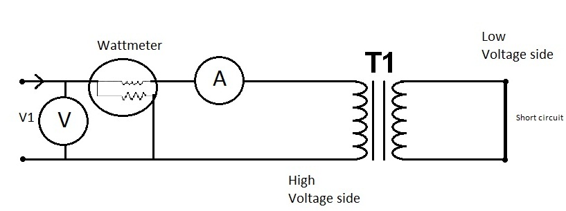
This test is performed to find out the copper losses and the series parameters (Req and Xeq) of the equivalent circuit of the transformer. This test is conducted on the HV winding side and LV winding in short circuited. The connection diagram is illustrated in Figure. A very low voltage (5-8% of the rated voltage) is enough to circulate the full load current under short circuit. The shunt branch parameters m,ay be neglected in this case as the I0 is very small (0.1 to 0.5%) under the condition of very low voltage. Whereas conducting the SC test, the voltage on HV winding side is slowly raised from zero to till the value transformer draws full load current. Record the meter readings.

Figure: Connection Diagram for Short Circuit Test
Voltmeter reading = Vsc volts
Ammeter reading = Isc Amps
Power input = Psc Watts
The wattmeter reads the copper losses (Psc), watts
Zeq = Vsc /I sc
R eq = Vsc/ (I sc )2

Req and Xeq are the ohmic values referred to the HV winding side.
Therefore short circuit test and open circuit test gives the parameters of the equivalent circuit of the transformer and also the efficiency and voltage regulation of the transformer.