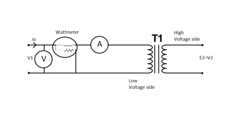
Open Circuit Test:
This test is performed to determine the core losses and shunt branch parameters Gi and Bm of the equivalent circuit of the transformer. This test is performed on the low voltage winding side whereas high voltage winding is kept open circuited. The connection diagram is illustrated in the Figure. Rated voltage is applied to the low voltage winding and meter readings are recorded.
Voltmeter reading = V1 Volts
Ammeter reading = I0
Amps Power input = P0 Watts
The no load current I0 drawn by the transformer in very low usually 2-6% of the rated current. The winding resistances and reactances are of extremely low ohmic value. Thus, ohmic losses may be neglected.
The equivalent (approximate) circuit is illustrated in Figure

Figure: Equivalent Circuit for Open Circuit
The watt meter reads the core losses (P0), watts :
(V1 )2 Gi = P0
Gi = P0 /(V1 )2
Y = I0 /V1

We must know the Gi and Bm are referred to the low voltage winding side. We may easily transform them to the HV winding side.