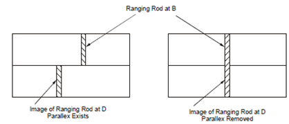
Offsetting by Optical Square:
If location D is fixed, denoting some important ground fixture, e.g. an electrical pole and offset is required from it on survey line. A surveyor aligns the instrument along AB and then moves sideways along line AB, till, once again, the ranging rod at B and image of D coincide locating the position of C on ground such in which CD is perpendicular to AB. The position of C is transferred on ground along with the help of the plumb bob that was hanging from the centre of instrument.

Figure(b): Offsetting by Optical Square
The continuous use of optical square over a period of time and the rough handling of instruments may cause the included angle between the mirrors M1 and M2 to change from original 45o. This will induce errors within setting the offsets. If the angle becomes, say, 40o, the offset will be at 80o in place of 90o along with the survey line, although if involved angle becomes 50o, the offset angle becomes 100o. The instrument could be tested for accuracy and adjusted extremely simply by procedure described in following paragraph.