Application Of Particle Swarm Optimisation Algorithm In Reliability Optimisation Problem
A gas turbine system has been studied in such section to relevant information pertaining for the functional performance of the system with its system dependability or reliability is explained also. The most normally witnessed gas turbine system is as given:
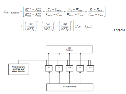
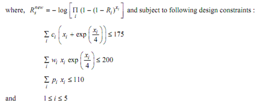
Seem the over speed protection system for a gas turbine as represented in following diagram. The over speed detection system is similar as it is depicted in diagram, in most of the gas turbines. Whereas operating it, whenever an over speed happens it is essential to cut off the fuel supply. For this cause, five control valves (V1-V5) should be closed from security point of view. Thus, control system can then be modeled like five stage series system. The objective is to find the number of redundant components at all stages i, weight, subjected to design constraints on the cost and the product of volume and weight. The objective function for this specific system is as given:

Figure: The Over-speed Protection System of a Gas Turbine

Here,
ci = Cost of all components in subsystem i,
i = Index for sub-systems, i = 1 . . . s,
pi = weight-volume of all components in subsystem i,
wi = Weight of all components in subsystem i,
ci = Cost of all components in subsystem i,
Ri = Reliability of all components in subsystem i,
Pmax = Maximum weight-volume of system,
Pmin = Minimum weight-volume of system,
Wmax = Maximum weight of system,
Wmin = Minimum weight of system, and
Δw, Δp and Δc = Magnitude of cost, weight and weight-volume constraint violation
The factors exp(xi/4) xi in Eqs. 24 and 25 accounts for the interconnecting hardware.
The innovative problem was presented by Tillman. The problem's objective function has been appropriately modified to combine multiple objectives related with the components. Moreover, a self adaptive penalty function is embedded also in function of objective consequently best solution is searched effectively and efficiently by the penalizing in-feasible solutions. For the five stage sequence gas turbine system the input data is describe in Table no.4.
To implement the customized Particle Swarm Optimization algorithm in aforementioned reliability optimization problem and a solution string, represented in diagram, has been constructed here, xi,j = Number of redundant component j utilized in subsystem i.
|
x1
|
x2
|
x3
|
....
|
....
|
xi
|
....
|
xs
|
Figure: showing of a Solution String that is employed in the modified Particle Swarm Optimization Algorithm
Table no.4: Input Data for Gas Turbine System
|
j
|
Rij
|
pij
|
P
|
cij
|
C
|
wij
|
W
|
|
1
|
0.80
0.85
0.90
0.65
0.75
|
1
2
3
4
2
|
110
|
7
7
5
9
4
|
175
|
7
8
8
6
9
|
200
|
|
2
|
|
3
|
|
4
|
|
5
|
In order to implement the Particle Swarm Optimization algorithm in the aforementioned Gas turbine system illustrated pseudo-code described in Programme no.4.
Start
initialize the population
while (iter < max_iter)// whereas termination criterion is not reached
do
for (i = 1 to number of particles)
evaluate Jobj_function //compute the objective function for all particles
Update pid and pgd // update the global best and self best position
for (j=1 to number of dimensions)
Calculate new velocity according to eq15 without previous velocity term
// compute velocity of particle using chaotic random generators.
if (vij = 0)
if (crand3(.)<0.5)
vij = crand4(.)*v //velocity is reinitialized
else
vij = - crand5(.)*v //velocity is reinitialized
endif
endif
vij = sign(vij)*min (abs(vij , vmax))//if velocity goes above vmax
//then it is allocated the velocity equal to vmax
update the particle's position Xij
increase j
increase i
//calculate Time Varying Acceleration Coefficients for next
//generation
Update the parameters ?1 and ?2 as per eqn(21) and (22)
iter=iter+1;
enddo
end
Programme no.4: Pseudo Code for the Particle Swarm Optimization Applied to the Reliability Optimization Problem or ROP.