Mutual Inductance:
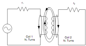
Two circuits can be coupled magnetically as illustrated in Figure. Here coil1 and coil 2 have magnetic coupling in between them. Coil1 has N1 number of turns and coil 2 has N2 number of turns. Alternating source Vs establishes an alternating current i1 which generates an alternating flux Φ1 in coil1. Φ11 is that portion of flux Φ1 which completes its magnetic path around coil1 and the other part Φ12 is the mutual flux linked with coil 2.

Figure: Magnetic Coupling
So, Φ1 = Φ11 + Φ12
The mutual flux Φ12, which is alternating in nature, generates an induced e.m.f e2 in coil 2 according to Faraday's law of electromagnetism,
e2 = N (d φ12/ dt )
Again e2 is proportional to the rate of change of i1, i.e.
e 2 ∝ di1/ dt
or, e2 = M12 (di1 /dt)
where M12 is the constant of proportionality termed as mutual inductance between two coils. Its unit is Henry (H).
From Eqs. (13) and (15) we obtain,
N2 (d φ12/dt) = M12 (di1 /dt)
or,
M12 = N2 (d φ12/ di)
The induced voltage e2 generated in coil 2 causes alternating current i2 to flow in coil 2. Current i2 generates an alternating flux Φ2 in coil 2. Out of flux Φ2, a portion Φ22 completes its path around the coil. The other portion Φ21 is linked with coil 1 and it generates an induced e.m.f given by
N1 (d φ21 / dt) = M 21 (di2 /dt)
So, from Eq. (18), we obtain,
M 21 = N1 (d φ21 /di2)
If the flux and current are having a linear relationship which we consider to be true, Eq. (17) and Eq. (19) may be written as
M12 = N2 (φ12 /i1)
and
M21 = N1 (φ21/i2)
Suppose that the permeability of the mutual flux path is constant, we have
M12 = M 21 = M