G01 Linear Interpolation
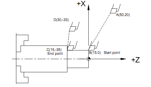
Like in this case of machining centres G01 is used for specifying linear interpolation at a specified feed rate. The specified feed rate is considered vectorial from the start point to the end point while the individual axes speed may vary. A typical motion involving G00 and G01 is shown in Figure 34. The actual programming modes that are possible are shown below for radius programming:

Figure 34: Example for Linear Interpolation with Feed using Radius Programming
Programming from A-B-C-D (Radius Programming)
Absolute Mode
N035 G00 X15.0 Z 0.0;
N040 G01 X15.0 Z-35.0 F120; N045 G00 X 30.0 Z-33.0;
Incremental Mode
N035 G00 U-35.0 W-20.0; N040 G01 U0 W-35.0 F120; N045 G00 U 15.0 W 2.0;
Mixed Mode
N035 G00 U-35.0 Z 0.0; N040 G01 U0 Z-35.0 F120; N045 G00 U 15.0 Z-33.0;
Or
N035 G00 X15.0 W-20.0
N040 G01 X15.0 W-35.0 F120; N045 G00 X 30.0 W-2.0;
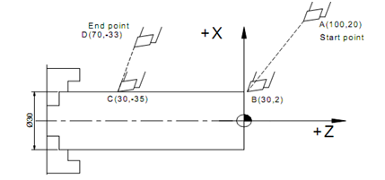
In the case of radius programming, the X-axis dimensions given are directly the radial values as shown in Figure 34. However, in the case of diameter programming all the X-values are given as the diameter which means all values including the rapid motions will have to be doubled. An example is shown below (Figure 35) to demonstrate the concept.

Figure 35: Example for Linear Interpolation with Feed using Diameter Programming
Programming from A-B-C-D (Diameter Programming)
Absolute Mode
N035 G00 X30.0 Z2.0
N040 G01 X30.0 Z-35.0 F120
N045 G00 X70.0 Z-33.0
Incremental Mode
N035 G00 U-70.0 W-18.0
N040 G01 U0 W-33.0 F120
N045 G00 U40.0 W-2.0