Continuous Beams:
Now, that will be explained through an example of a continuous beam given below.
Moment Distribution Method Applied to Continuous Beam
Example
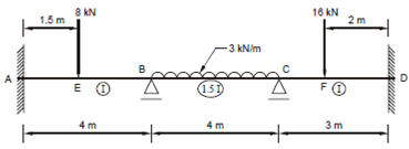
A continuous beam fixed at ends A and D is loaded as shown in Figure 8. The end spans AB and CD have moment of inertia I and for the middle span BC the moment of inertia is 1.5 I. It determines the moments and reactions at the support and draw the BM and SF diagrams.

Figure 8
Solution
Step 1 The fixed end moments for each member is determined below:
Member AB MFAB = 8 × 1.5 × (2.5)2/42 =-4.6875 kNm
MFAB = 8 × (1.5)2 × 2.5/42 =-2.8125 kNm
Member BC MFAB = 3× 42/12 =-4.0 kNm
MFCB = 3× 42/12 = +4.0 kNm
Member CD MCD =16x1x22/32 = -7.1111 kNm
MCD =16x12x2/32 = +1.7778 kNm
Step 2
A distribution factors for members meeting at each joint are determined below:
At joint A
A joint A is fixed and there is just one member AB, hence, no distribution is required here.
At joint B
The joint B is easily supported and two members BA and BC meet at this joint
K BA = I/ l = I/4
K BC = 1.5 /I
∴ By Eq. (3.16), distribution factor for BA,
= K BA/∑ K = (I/4)/((I/4)+(1.5 I/4)) =0.4
Distribution factor for BC, = K BA/∑ K = (1.5I/4)/((I/4)+(1.5I/4)) =0.6
At joint C
There are two members CB and CD and we have KCB = 1.5 I/4
And KCD =I/3.
and DFCB =(1.5I/4)/((1.5I/4)+(I/3)) =0.53
and DFCB =(I/3)/((1.5I/4)+ (I/3)) =0.47
At joint D
Since the joint is fixed there will not be any distribution of moment at the only member DC meeting at this joint (DF = 0).
The actual process of distribution of moments begins. This is usually done in a tabular form. Various authors have suggested various forms. To facility of compute for a continuous beam the simple scheme in Table appears to be good enough.