Nesting of Flat Patterns (Blanks)
Nesting of flat patterns is important in sheet metal CAPP as it directly governs material utilization, productivity and cost of production. Nesting is the placement of several similar/dissimilar flat patterns (blanks) on a larger sheet/strip to maximize material utilization and minimise scrap.
Apart from material utilization, many technological constraints need to be taken into consideration during nesting [4][6]. Important among them are as under:
- Manufacturing process, Machine
- Blanking press, Flame cutting, Laser/Water jet cutting
- No. of dies for blanking Presses
- Sheet/Strip size - (Length, Width)
- Orientation of bend with grain direction
- Clearances (bridge) between band sheet edges.
- Types of blanks - similar/different geometry.
- Preferred shop practices.
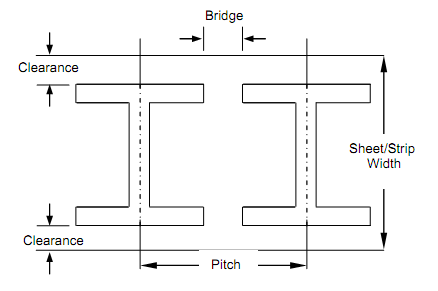
Given fig shows a typical blank placement on sheet indicating the clearances (Bridge) between blanks, sheet edges, pitch of the layout and orientation of blanks. The bridge allowances are selected by the CAPP system database created from handbook recommendation and heuristics. The values are dependent upon the material of the part, hardness of sheet, grain orientation and sheet thickness.
The problem of optimal placement of parts on sheet (Nesting) is a very complex mathematical problem. Researchers world wide have developed several computer algorithms to solve this problem using various techniques like heuristics, knowledge based (Expert System), statistical techniques and recently the genetic algorithms.

Figure : Blank Layout Parameters
Problems of nesting rectangular sheet is relatively simple but nesting of irregular geometry blank parts onto rectangular sheet is very complex.
Given the parts to be nested, their CAD models, number and sheet size, the CAPP system automatically designs and displays optimal nesting layout. Various cases can broadly fall into four categories.
- Single Product, Single Row (SPSR)
- Single Product, Multi Row (SPMR)
- Multi Product, Single Row (MPSR)
- Multi Product, Multi Row (MPMR)

Tilting Angle : angle = 20o Tilting Angle : angle = 204o
Slitting Width = 157.79 Slitting Width = 157.254
Pitch = 105.326 Pitch = 110.300
Utilisation Ratio = 0.4272 Utilisation Ratio = 0.4094

Tilting Angle : angle = 60o
Slitting Width = 119.663
Pitch = 155.020
Utilisation Ratio = 0.3828
Figure : Typical Part and its Layouts
Given figure shows a typical part and its various layouts generated with reported material utilization ratio. The user can select the desired layout based on the machine and shop constraints.