Flat Pattern Development
Flat pattern development is the first important step in sheet metal die design and production. Flat patterning essentially means unbending of the 3D sheet metal part onto a flat sheet to determine the blank shape and size, which is produced by blanking operation. For a 3D part, the process of flat pattern development is quite complex as it needs the calculation of bend allowance during the unfolding of part surface (walls) and mapping of features like holes, slots, cutouts, etc. on planes.
Traditionally the flat pattern design and drawing is done by process planning engineers using some thumb-rules. It is thus slow, tedious and error prone.
CAPP packages provide a module for automated flat pattern development from the 3D CAD part model. It involves the following steps [2] :
- Retrieval of feature based CAD part model
- Identification of base face and other faces to be unbent
- Gathering parameters of bend from the part database
1.Constituent faces
2. Basic feature length
3. Bend angle
4. Bend radius
5. Material
- Calculating bending allowances (BA) and Bending Compensation (BC)
- Computing sizes of flat pattern blanks
- Creating CAD model of flat patterns

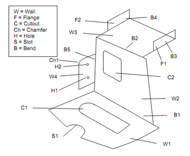
Figure : A Sample Part
Given figure shows a typical 3D model of the sheet metal part with Base Face and other bent faces with relevant data. The CAPP system uses Sach's Rule for computation of Bend Allowance using the empirical equation as under
Bend Allowance (BA) = θ (r + kt)
where θ = Bend Angle in radians,
r = inner radius of the bend,
k = empirical constant, and
t = sheet thickness.
The constant K varies between 0.2 to 0.5 based on material type, hardness, inner radius of the bend and stock thickness. It is stored in the CAPP database.

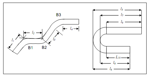
Bending Nomenclature : r = bend radius, t = stock thickness, l = length of straight section, m = mould line dimension, and A = bend angle.

(a) Part Measurements (Except of a 180-degree bend). "Outer" (l1 and l2) for bend "B1", "Inner" (l2 and l3) for bend "B2" and; "Straight" (l3 and l4) for bend "B3", and
(b) Part Measurements for a 180-degree Bend. "Outer" (l5 and l6); "Inner" (l7 and l8) and; "Straight" (l9 and l10)
Figure: Bend Feature Nomenclature
Bend Compensation (BC) is the length to be subtracted from the specified lengths of the connected sections when calculating the blank length. Figure shows the nomenclature for specifying section lengths and type of bending viz., 'Outer', 'Inner' and 'Straight' [5]. For example, the blank length for sections with l1 and l2 is .
Blank Length = l1 + l2 - B2
CAPP system will automatically compute BC based on cases enumerated below :
(a) BC is calculated as per the three cases - outer, inner and straight bond.
(b) BA is calculating by earlier.
Outer Bend
BC = 2 (r + t ) tan ( θ/2) - BA
Inner Bend
BC = 2 tan ( θ/2) - BA
Straight Bend
BC = - BA
Given figure shows the flat pattern developed from the CAD model of the part illustrated in Figure

(a) (b) (c)

(d) (e) (f)
Figure : The Unfolding Steps for the Sample Part