Die Design
The optimal blank layout generated by the nesting module of CAPP software is used further for the die design. There are three important sub stages in automated die design.
Strip Layout
- Die Layout
- Design/Selection of Punch/Die elements
CAPP system has some rules derived from practice which carry out technological checks at every stage to ensure the feasibility of die design. These essentially include data range checks and production constraints.
In the strip layout module, the type of die is selected depending upon sheet thickness, product accuracy, production quantity and complexity of the part/blank. Strip layout is automatically created by the CAPP system considering number of stages in the progressive dies; pitch, slitting width and the punch profile details in each stage. For compound dies, such splitting of geometric data over stages is not required. Based on the strip layout, the die layout module of CAPP system carries out various tasks such as computation of force and center of pressure, selection of die and punch material, stripper, punch holders, back up plates, springs, etc..
The next stage is to design/select standard punches, die blocks, check them for strength (feasibility), etc. The die design module converts the strip layout into actual die (Tool) by generating an assembly of punches and dies and creating the actual die solid model in the CAD system. CAD model of the die is automatically generated by the system by Virtually Assembling CAD models of various die components. Die drawings and bill of material are the outputs generated by the CAPP system.

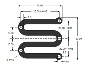
Figure : Component for Die Design

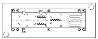
Figure: Strip Layout
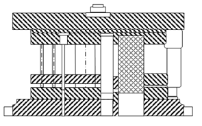
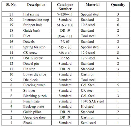
Given fig shows a typical sheet metal part to be produced. Figure shows the strip layout for the progressive die. Given figure shows the die drawing and BOM for the progressive die to manufacture this component.


Figure : Die Design and BOM