CAD Modeling of Parts
To model a sheet metal part, following data needs to be provided by the user.
- Part Name
- Part Number
- Part Material
- Part Geometry
User is provided with a GUI to input above information. Part geometry data can be inputted by a User friendly CAD modeling interface or imported from a CAD package in the form of standard CAD file in DXF/IGES/STEP format.

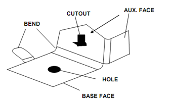
Figure (a) : Part Modeling Philosophy

Figure (b) : Typical Parts Modeled
Given figure shows the approach followed in CAD modeling of a sheet metal part . The part model is conceived to have a Base Face to which other Auxiliary faces are "Appended". Base Face and the Auxiliary Faces are joined by a "Bend" feature having specific feature parameters like bend radius and bend angle.
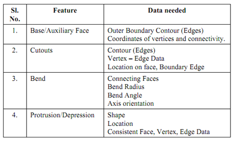
Table lists typical part features and the data required for their geometric modeling.
Table

The geometric data can be provided by the user interactively using mouse or by using custom feature design templates. Given figure shows typical part models created during the modeling session of a sheet metal CAPP system.
The CAD models are internally stored in the form of feature based CAD files following STEP alike data format. These are used in further process planning operations.