Preamplifiers and Amplifiers:
Radiation detector outcome signals are commonly weak and needed amplification before they could be used. Within radiation detection circuits, the nature of the input pulse and discriminator determines the features in which the preamplifier and amplifier must have. There are two stages of amplification are used in most detection circuits to rise the signal-to- noise ratio.
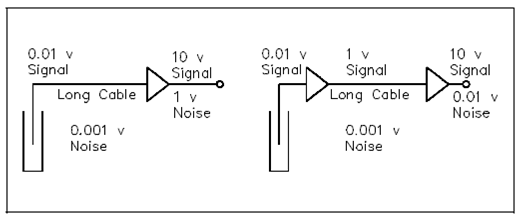
Below figure displays how a two-stage amplifier increases the signal-to-noise ratio.

Figure: Single and Two-Stage Amplifier Circuits
The radiation detector is located a few distances from the readout. The shielded coaxial cable transmits the detector outcome to the amplifier. The output signal of the detector might be as low as 0.01 volts. An overall gain of 1000 is required to increase this signal to 10 volts that is a usable outcome pulse voltage. Those are always a pickup of noise in the long cable run and this noise could amount to 0.001 volts.
The 0.01-volt pulse signal would be 10 volts if all amplification were completed at the remote amplifier, and the 0.001 noise signal would be 1 volt. That is a signal-to-noise ratio of 10 and could be significantly decrease through dividing the total gain among two stages of amplification. The preamplifier located near the detector and a remote amplifier could be used. A preamplifier virtually eliminates cable noise since of the short cable length. If, for an overall gain of 1000, the preamplifier has a gain of 100 or the amplifier has a gain of 10 and the outcome signal from the preamplifier is 1 volt. The signal transmitted through the long cable run still picks up the 0.001-volt noise. An amplifier amplifies the 1.0- volt pulse signal and the 0.001-volt noise signal through a factor of 10. The conclusion is a 10-volt pulse signal and a 0.01-volt noise signal. This provides a signal-to-noise ratio of 1000.