Discriminator Circuit:
A discriminator circuit chooses the minimum pulse height. While the input pulse exceeds the discriminator preset level and the discriminator produces an output pulse. The discriminator input is generally an amplified and shaped detector signal. This signal is an analog signal since the amplitude is proportional to the energy of the incident particle.
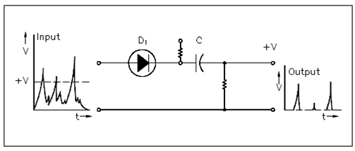
The biased diode circuit is the easiest form of discriminator. Below Figure displays a biased diode discriminator circuit along with its related input and output signals.

Figure: Biased Diode Discriminator
Diode D1 is display within its cathode linked to a positive voltage source +V. A diode cannot conduct unless the voltage across the anode is positive along with respect to the cathode. Since long as the voltage at the anode is less than in which of the cathode, diode D1 does not conduct, and there is no outcome. At a few points, anode voltage exceeds the bias value +V, and the diode conducts. The input signal is permitted to pass to the outcome.
Above figure describes input and output signals and how the discriminator acts to eliminate all pulses which are below the preset level. The outcome pulses of this circuit have the similar associative amplitudes as the input pulses.