Introduction to 2051 Microcontroller:
Microcontroller Architectures
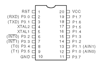
The 2051 microcontroller is a complex integrated circuit which is programmable. You can give it a set of commands to follow and it will run through those of the commands and do accurately what you want it to do. This section will give a rapid overview of the pins of the 2051 and in the later we shall discuss how to program the 2051. The 2051 is illustrated below.

Figure: 2051 Microcontroller Pin Configuration
Pin 1 is reset. This pin can be utilized to force the 2051 to start over at the starting of the program. Pin 2 and Pin 3 can be utilized to communicate with the computer or other devices (RXD is receive and TXD is transmit). Pin 2 and Pin 3 are also part of Port 3. Port 3 involved P 3.0, P 3.1, P 3.2, P 3.3, P 3.4, P 3.5 and P3.7 (there is no P 3.6). Usually these pins are used as general input/output pins. They can be associated to LEDs to turn them on and off (this would be by using them as outputs). Or they can be linked to switches so that the 2051 can look and see if a user has turned a switch on or off (this would be by using them as inputs). Pins 4 and 5 are associated to the 11.0592 MHz crystal. The 2051 uses this crystal to make a clock. The speed of the crystal find out the speed that the 2051 runs at. You can write programs run faster by using a faster crystal such as 24 MHz. Pin 10 is the ground connection for the 2051. Pins 12 to 19 make up Port 1. It is another set of pins that can be utilized as general inputs and outputs. Pins 6, 7, 8, 9, 12 and 13 also have other possible uses that we will not get into here.