Contouring Parameter in Mastercam
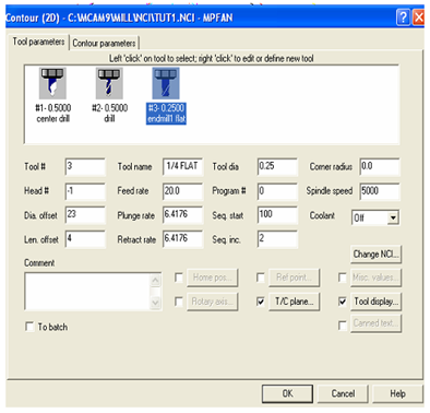
After successfully completing the drilling operations, it is necessary to carry out the contour machining of the profile by using a 0.25 inch end mill. For this purpose select the contour option in the tool path menu, that will bring the user to select the geometry for the contour. It may be done by the Chaining option, where the user can select the starting geometric element, such that the system will automatically select all the connected entities. Once you complete the contour selection process, it automatically opens the contour parameter dialogue box as illustrated in Figure 36 with the cutting tool selection tab.

Figure 36: The Contouring Parameter Dialogue Box in Mastercam
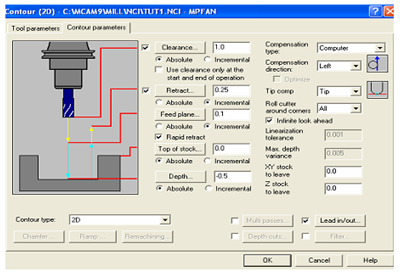
We follow the same procedure as earlier and select the 0.25 inch flat end mill as the tool to be used for this operation, and then continue with the contouring parameter tab. It allows us to give the contour parameters such as clearance plane, retract plane position, top of the work piece position, depth of the contour, where the tool should be positioned with respect to the contour, and other parameters such as depths of cut and finish cuts required if any. Make all the selections as illustrated in Figure 37.

Figure 37: Contour Parameter Dialogue Box in Mastercam