Motion Group, G00, G01, G02, G03
Of all the G-codes available in a controller these are the most widely used codes in a given program. All the codes in this group are modal and can be cancelled by any of the codes within the group.
Rapid Positioning, G00
This code is used for specifying the movement at the maximum possible feed rate. The tool is normally moved at the maximum possible feed such as 8000 or 40 000 mm/min along the axes involved for achieving the position programmed. In this code the path taken by the tool to reach the programmed point is not important since the tool is not supposed to do cutting during this code.
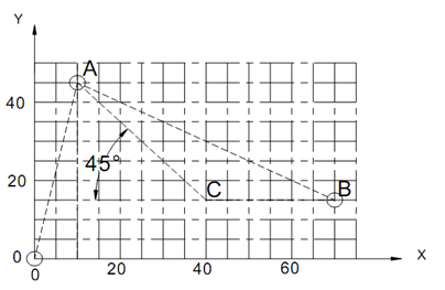
Referring to Figure 7, the tool is currently at position A and it is required to move it to position B. For this, the program block in absolute coordinates would be
N15 G90 G00 X80.0 Y15.0;

Figure 7: Positioning, Preparatory Function G00
The path of the tool from A to B can be either through the shortest path, or alternatively the tool will start moving in all axes at the maximum speed possible thereby going through a 45 path as shown in Figure 4.7. When one of the coordinates is satisfied, then the tool will start moving in the other axis till the programmed position is satisfied. Though the above example shows a movement in two axes, it is also possible to have the same in all three axes simultaneously.
The program block in incremental coordinates would be
N15 G91 G00 X60.0 Y-30.0;
Linear or Straight line Interpolation, G01
Linear or Straight line Interpolation is generally used when the material is being cut by the cutting tool. In this case, the tool will move along the programmed straight line with the specified feed rate. In this case, the controller moves all the three axes at a rate such that the resultant velocity along the line matches the programmed feed rate.

Figure 8: Linear Interpolation, Preparatory Function G01
Absolute programming O to A to C to B (Figure 8)
N110 G90 G00 X10.0 Y45.0 Z2.0
N115 G01 Z-8.0 F300;
N120 X40.0 Y15.0;
N125 X70.0;
Incremental programming O to A to C to B (Figure 8)
N110 G91 G00 X10.0 Y45.0 Z2.0
N115 G01 Z-10.0 F300;
N120 X30.0 Y-30.0;
N125 X30.0;
Circular Interpolation, G02 / G03
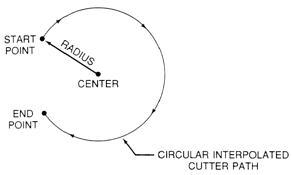
Circular interpolation is used to generate arcs in a single plane. The codes used are G02 for clockwise motion and G03 for anti-clockwise motion. The direction of motion is established by looking in the negative direction of the axis perpendicular to the plane. The format to be used is
G02 X---Y--- I--- J--
Here X and Y refer to the end point of the arc, while I and J are position of the center measured incrementally from the start point of the arc. I refer to the distance along X-axis while J is for the motion along Y-axis. I and J are always specified in incremental whether the program is written in absolute or incremental programming.
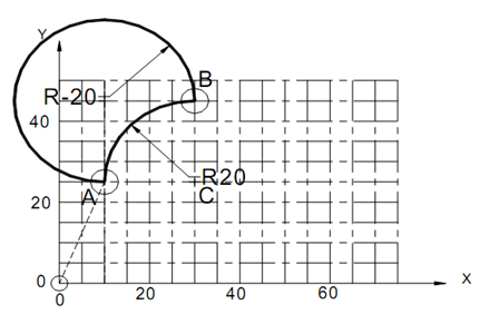
Referring to Figure 9, when the motion is from A to B in XY plane, the program block would be, as per ISO,
N125 G02 X30.0 Y45.0 I20.0 J0 F250;
But, if the motion were from B to A, then it would be
N125 G03 X10.0 Y25.0 I0 J-20.0 F250

Figure 9: Circular Interpolation, Preparatory Function G02/G03
It is also possible to specify the radius of the arc in place of the center coordinates using I and J. In that case, R word address is used for specifying the radius. The specification will then be for the above case,
N125 G02 X30.0 Y45.0 R20.0 F250;
However, looking at Figure 10, it can be noticed that there are two possible arcs that can be drawn using the given information, since the center of the arc is not precisely located. It can be noticed that one arc is smaller (less than 180°) and the other larger (greater than 180°). To check for the correct arc, the nomenclature as adopted is that the radius of the larger arc is specified with a negative sign for the radius.

Figure 10: Circular Interpolation using R Word Address
It is possible to draw a complete circle using the circular interpolation commands G02 and G03. However, in that case the center of the coordinates should be specified using I and J and not by the radius, R. If radius is to be used, then the arc may be broken into semi-circles and would have to be programmed in two blocks.
Above example used the default XY plane. It is also possible to use the plane selection codes to draw arc in XZ and YZ planes with G18 and G19 respectively.