Determination of Instantaneous Centres in a Mechanism:
Kennedy's theorem may be utilized for determining all of the instantaneous centers in a mechanism. It can be verified with the help of some examples.
Example
In a four bar kinematic chain O2A BO4, link O2O4 is fixed. The length of links is as:
O2A = 20 cm, AB = 45 cm, O4B = 33 cm. O2O4 = 22 cm and ∠ O4O2A = 120o
AC = 33 cm and O4D = 21 cm
If crank O2A rotates at 300 rpm in counter clockwise sense, locate all of the instantaneous centres and find out :
(1) angular velocity of link O4B
(2) velocity of points C & D as illustrated in figure
Solution
Nos. of instantaneous centros,
N = (4 × 3 )/2= 6 .
Table of I.Cs
I12 I13 I14
I23 I24
I34
Since a first step, the configuration diagram is plotted by selecting appropriate scale.
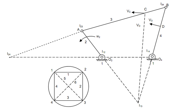
Out of these 6 instantaneous centres four may be recognized easily by looking at the configuration diagram. These are I12, I23, I34 & I14 at points O2, A, B & O4 respectively. The left over two instantaneous centres I13 and I24 may be find out in a systematic manner by utilizing circle diagram. A circle of any arbitrary radius is drawn primary. All of the links are represented on this circle through equally spaced points at the circumference as illustrate in figure. On the circle the lines joining the points represent relative instantaneous centres. The lines that represent known instantaneous centres are drawn primary. For finding I13, join points 1 & 3 in the configuration diagram. This line is common side to two triangles. Triangle 1, 2, 3 shows three instantaneous centres I12, I23 and I13. Likewise, triangle 1, 3, 4 shows I14, I34 & I13. According to Kennedy's theorem I12, I23 & I13 must lie on a straight line. Also I14, I34 & I13 must lie along a straight line. I13 will be point of intersection of two lines drawn joining I14 along I34 and joining I12 & I23. A line joining I12 & I23 is drawn & another line joining I14 and I34 is also drawn. These two lines intersect at I13 as illustrated in Figure. Now points 2 & 4 are joined. This line shows I24. This is common line to the two triangles which is represented through 1, 2, 4 and 2, 3, 4. A line is drawn joining I12 & I14. Another line is drawn joining I23 & I34. These two lines shall intersect at point I24.

Determination of Instantaneous Centres in a Mechanism
Now all of the six instantaneous centres have been find out.
To resolve angular velocity of link 4, I24 is needed that connects link 4 with 2. As angular velocity of link 2 is called as I24 may be considered along links 2 and 4. Letting I24 with link 2, the velocity of I24 shall be equal to ω2 × O2 I24
or,

I24 may be considered along link 4 also.

or

∴ Velocity of point D, VD = 4.78 m/s.
It's direction is perpendicular to O4D in the sense of rotation. To find out absolute velocity of C, I13 can be utilized

The direction of VC is perpendicular to the line I13C.