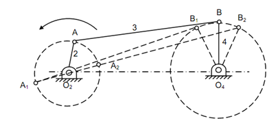
Crank-lever Mechanism or Crank-rocker Mechanism:
This mechanism is illustrated in given figure. In this case for each complete rotation of link 2 (called a crank), the link 4 (known as lever or rocker), makes oscillation among extreme positions O4B1 and O4B2.

The position of O4B1 is achieved when point A is A1 whereas position O4B2 is achieved while A is at A2. It can be observed that crank angles for the two strokes (forward and backward) of oscillating link O4B are not similar. It can also be noted down that the length of the crank is very short. If l1, l2, l3 and l4 are lengths of links 1, 2, 3 and 4 respectively, the proportions of the link can be as follows :
(l1 + l2 ) < (l3 + l4 )
(l2 + l3 ) < (l1 + l4 )