The Ideal Diode as a Rectifier
Generally Rectification is defined as the procedure of converting an alternating current to a unidirectional current. A rectifier device substantially conducts current in one direction simply. An ideal rectifier diode will be an open circuit in one direction & short circuit in the other direction. It also will not dissipate power at the time of rectification procedure.
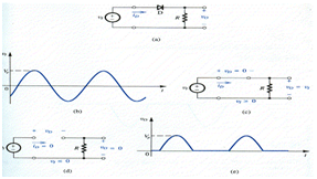
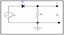
The rectifier circuit indicated in the diagram (a). This circuit consists of series connection of a diode D & a resistor R. Allow the input voltage be sinusoid as indicated in diagram (b) and let the diode to be ideal. At the time of the positive half cycle of the input sinusoid, the positive vI will reason of current to pass through the diode in its forward direction. This follows that the diode voltage VD will be very little that means ideally zero. Therefore the circuit will have the equivalent indicate in the diagram (c) and the output voltage VO will be equivalent to the input voltage vI. Alternatively, At the time of the negative half cycle of vI the diode will not conduct .Therefore the circuit will have the correspondent show in the diagram (d), and VO will be zero .Therefore, the output voltage will have the waveform indicated in diagram (e).Note down that while VI alternates in polarity and contain a zero average value, VO is unidirectional and contain a dc component or a finite average value. Therefore the circuit of diagram (a) rectifier the signal and thus is said a rectifier.
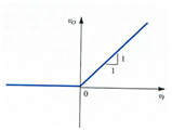
Example: For the given circuit draw transfer characteristic V0 VS VI
Sol: