(A) Voltage Source to Current Source:
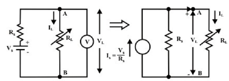
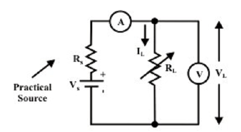
For the practical voltage source shown in figure (a), the load current is computed as

Note that the highest current delivered by the source whenever RL = 0 (under short-circuit situation) is given by

A simple current divider circuit containing two parallel branches as shown in figure (b) can recognize by the above equation.
Remark:
A practical voltage source with voltage Vs and an internal source resistance RS can be substituted by an equal practical current source with a current

and a source internal resistance RS as shown in figure (b)

Figure: Source conversion
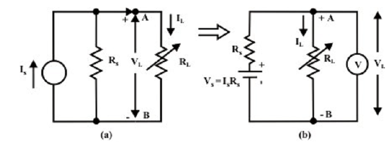
(B) Current source to Voltage Source:


The above equation symbolizes output from the voltage source across a load resistance and this act as a voltage divider circuit. Figure (b) shown below explains the condition that a voltage source with a voltage value VS = ISRS and an internal source resistance RS has an equal effect on the similar load resistor as the current source shown in figure (a).

Remarks on practical sources:
(i) The open circuit voltage which emerges at the terminals A & B for two sources (i.e., voltage & current) are alike (that is, IS).
(ii) Whenever the terminals A & B are shorted by an ammeter, the shot-circuit outcomes similar in both situations (that is IS).
(iii) When an arbitrary resistor (RL) is connected across the output terminals A & B of either source, the similar power will be dissipate in it.
(iv) Sources are equal only as concerns on their behavior at the external terminals.
(v) The internal behavior of both sources are quite dissimilar (that is, whenever open circuit voltage source does not dissipate any internal power whereas the current source dissipates. The reverse condition is noted in short-circuit situation).