Types of linear ICs
There are several situations in which linear integrated circuits can be used. Linear ICs include regulators, amplifiers, timers, multiplexers, and comparators.
The operational amplifier
An operational amplifier, or op amp, is a specialized form of the linear IC. The op amp comprises of several transistors, diodes, resistors, and capacitors, interconnected such that high gain is possible over the wide range of frequencies. An op amp might comprise an entire IC. Or, an IC may consist of 2 or more op amps. Therefore, you will sometimes hear of dual op amps or quad op amps. Some of the ICs have op amps in addition to several other circuits.
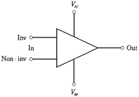
An op amp has 2 inputs, one noninverting and 1 inverting, and 1 output. When a signal goes into noninverting input, output is in phase with it; when signal goes into inverting input, output is 180 °out of phase with it. An op amp has 2 power supply connections, one for emitters of transistors (Vee) and one for the collectors (Vcc).
The op amp denoted by is a triangle. The output, inputs, and power supply connections are drawn as lines emerging from it, as shown in the figure given below. You do not have to be concerned with details of circuit inside the triangle.

Figure--Symbol for an op amp.Connections are discussed in the text.
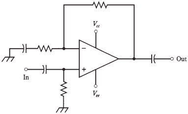
The gain characteristics of the op amp can be determined by external resistors. Basically, a resistor is connected between output and inverting input. This is called as closed-loop configuration. The feedback is negative; causing the gain of op amp to be less than it would be if there was no feedback.An amplifier can be very sensitive, overloading following circuits, generating too much noise, or producing useless responses.

Figure--Closed-loop op-amp configuration.
Open-loop op amps, when used at the low frequencies, have very high gain, and are prone to instability. They are quite noisy usually.

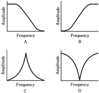
Figure--At point A, low-pass response; at point B, high-pass response; at point C, resonant peak; at point D, resonant notch.
The regulator
A voltage regulator IC acts to control output voltage of the power supply. This is important with precision electronic equipment. These ICs are available in different voltage and current ratings.Typical voltage regulator ICs has 3 terminals. They look like power transistors.
The timer
A timer IC is actually a form of oscillator. It generates a delayed output, with the delay being adjustable to suit the requirement of a particular device. The delay is generated by counting the number of oscillator pulses; the length of the delay can be adjusted by means of external resistors and capacitors.
The analog multiplexer
The analog multiplexer IC allows many different signals to be combined in a single channel by means of time-division multiplexing, in a manner similar to that used with the pulse modulation. An analog multiplexer can be used in reverse; then it works as a demultiplexer.Therefore, you will sometimes hear engineers talking about multiplexer/demultiplexer ICs.
The comparator
Like an op amp, a comparator IC has 2 inputs. The comparator does what its name implies: it compares voltages at two inputs (called as A and B). If the input at A is significantly larger than the input at B, the output will be around + 5 V. This is logic 1, or high. If input at A is not greater than input at B, the output voltage will be around + 2 V. This is designated as logic 0, or low.Voltage comparators are available for the variety of applications. Some of them can switch between low and high states at the rapid rate of speed; others are slower. Some offer low input impedance, and others offer high impedance. Some are intended for the audio or low-frequency use; others are fabricated for the video or high-frequency applications.Voltage comparators are used to actuate, or trigger, other devices like relays and electronic switching circuits.