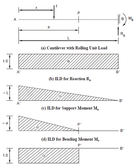
Influence Line Diagram for a Cantilever:
In this section, we shall explain how to draw the influence line diagrams for the support reactions and BM and SF at any point in a cantilever beam. You should verify all the steps yourself.
In Figure, the cantilever whose free end is A and fixed end B has a span of L.
Influence Line Diagram for Support Reactions
If a unit load moves from A to B along the beam, the vertical reaction RB at B remains constant and is equal to 1.0. However, the fixed end moment MB = - 1 × (L - x) = - (L - x) and hence the influence line coordinates for MB varies from - L at A to 0 at B. (You should carefully observe that it is just opposite to the BM diagram due to an unit load at A. Why?)
The IL Diagrams are shown at Figures (b) and (c).
