Influence Line Diagram For Bending Moment (Simply Supported Beam)
In the subsequent examples, influence line diagram for bending moment and shear force of some common structures are shown, and also how they are used in actual practice.
Example:
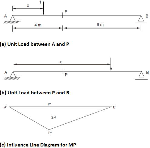
Draw the influence line diagram for bending moment at point P of the simply supported beam AB, display in Figure.

Solution
Case (i) : Load between A and P
If the unit load lies between A and P taking moment of forces to left of P, then BM at P is
MP = RA•4 - 1 × (4 - x) = (10 - x)/10 × 4 - (4 - x) = 6 x/10
This is a straight line A?P″ (Figure (c)) with IL ordinate = 0 at A (where x = 0) and IL ordinate = 2.4 at point P (where x = 4 m).
Case (ii): Load between P and B
When the load crosses the point P to the right, bending moment at P is
MP = RA • 4 = (10 - x)/10 × 4
This is again a straight line P″ B′ and the influence line ordinate is (10 - 4) /10× 4 = 2.4 at P; and at B the IL ordinate is (10 - 10)/10× 4 = 0.