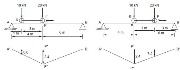
Calculate the maximum bending moment:
Two connected wheels (wheel base = 3 m) cross the beam in Figure 4 from left to right. The front wheel is carrying a load of 20 kN and the rear wheel 10 kN. Find the maximum bending moment at point P due to these wheels.

(a) (b)
Solution:
The influence line diagram is the most convenient method to solve such problems. It is obvious that since the maximum ordinate of the IL diagram is 2.4 (at point P), the maximum value of the bending moment will be obtained when one of the wheels is placed on this point P. There can be two possibilities, either the front wheel is at P (Figure 4 (a)) or the rear wheel is at P (Figure 4 (b)). Both are discussed below:
Case (i) : Front Wheel at Point P (Figure 4(a))
Rear wheel R will be 3 m to left of it (i.e. 4 - 3 = 1 m to right of A).
The ordinate at R (from similar triangles) is equal to 2.4 /4 ×1 = 0.6. Now by
Property (b) of the IL diagrams, the total BM at point P due to the two wheels will be MP = 20 × 2.4 + 10 × 0.6 = 54 kN m.
Case (ii) : When Rear Wheel is at P (Figure 4(b))
The front wheel F will be at F, i.e. 3 m to right of it.
The ordinate at F will be 2.4/6 × 3 = 1.2
Hence, BM at P will be MP = 20 × 1.2 + 10 × 2.4 = 48 kN m.
Hence, Case (i) will give the bigger value of bending moment, i.e. as shown in Figure and it will be 54 kN m.
This will be the maximum bending moment at P because of the wheels crossing across the span.