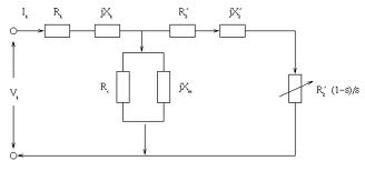
Equivalent Circuit:
We know that E1 / E2 = a and I2′ / I2 = 1 .
The impedance of the rotor circuit
Z¯2 = R2 + j S X 2
And Z2 = R2 + j X 2 (at standstill)
I¯2 = S E¯2/(R2 + j S X 2 )
Z 2′ = a2 R2 + j S a2 X 2
Z 2′ = R2′ + j S X 2′
which gives
I ′ = S E¯1/ (R2′ + j S X2 ′) = E¯1/(R′/S) + j X 2′
The Eq. (51) refers the rotor circuit to the stator frequency f. In referring the rotor circuit to the stator frequency the reactance becomes constant ( X 2′ ) and the resistance becomes variable ( R2′ / S ) . The equivalent circuit of an induction motor is illustrated in Figure .

If R2′ is separated from R2′ /S to represent the rotor copper loss as a separate quantity, the circuit model may be redrawn as Figure 5.16 where R2′ ((1/s)- 1) represents the mechanical output in electrical form.