Uses of Touch Trigger
The touch trigger probes may be utilized for the following applications:
1. Measuring dimensions
2. Assessing tolerance limits
3. Measuring tool offsets
4. Datuming the components on machine tool table
5. Digitizing the surfaces
Measuring Dimensions
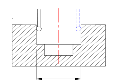
In order to measure a dimension, the probes can be utilized. The surface to be measured might be clean and should preferably cleaned by a flood of cutting fluid, which will help in flushing away any chips present on the surface as well as reducing the temperature of the surface. A typical instance of measuring slot width is illustrated in Fig 22. The part programming should be made such that the probe will touch the first surface and gets its coordinates (x1, y1, z1). Then the probe will touch the second surface and gets its coordinates (x2, y2, z2). Then the width of the slot can be calculated by the following equation (assuming the width is in the x direction) :
Width = x2 - x1

Figure 22: Use of Probe for Measuring the Width of a Slot
The dimensional measurement might be carried in two possible ways:
1. In-cycle measurement
2. Post-process measurements
The measurement of dimensions using probes in between cuts is termed as in-cycle measurement. This method helps in maintaining higher accuracies for critical dimensions. This can be done by writing the CNC part program along a spare cutting pass to be taken, if the part dimension is out of tolerance. Through before the measurement is done, the surfaces need to be clean without any chips by appropriate washing with a flood of the cutting fluid.
However, in the case of post-process gauging, the measurement is done after the machining is completed but still in the work holding fixture. If the part is out of tolerance, then remedial cuts can be programmed for critical dimensions bringing the part within specifications.
Measuring Tool Offsets
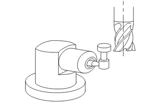
To measure the tool offsets the probe is slightly different from the one that is utilized for inspection. The tool measurement probe head is flat faced as illustrated in Figure 23 for machining centres. The probe is to be clamped at one ending of the machine tool table. After that the offsets are to be measured, the tool can be brought in contact with the probe tip in both the directions to obtain the tool offsets (length and diameter). The same probe can also be used for tool breakage monitoring as well.

Figure 23: Probe Type Used for Tool Offset Determination in Machining Centres
Datuming the Components on the Machine Tool Table
The setup of a workpiece on the machine tool table requires that the datum of the part is to be established before the part program can be activated. This is termed as datuming. Generally the dial gauges stationed on the spindle are used for the purpose. The touch trigger probes can be used in the place of dial gauges to identify the datum far earlier. The inspection probe can be made to touch the respective surfaces in order to obtain the datum.
Digitizing the Surfaces
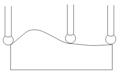
Unknown profiles and surfaces on the part can also be measured with the help of these probes. This procedure is termed as Digitising. The probe can be made to touch on the curve or surface at specified close intervals and the corresponding coordinates of the points can be recorded. Later on this data can be utilized to fit a closed curve or a surface to match the requirements of the part. A typical example of a digitizing process is shown in Figure 24.

Figure 24: Probe Used for Digitising a Profile