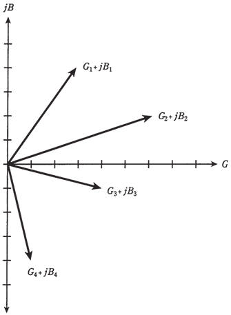
Vector representation of admittance:
The complex admittances can be shown as vectors, just in complex impedances. In the figure given below, the points from figure are rendered as vectors. Generally, longer vectors indicate the greater flow of current and shorter ones signifies less current.
Imagine that point moving around on GB plane, and think of the vector getting longer and shorter, and changing the direction. The vectors pointing northeast, or upwards and to right, correspond to the conductance and capacitances in the parallel. Vectors pointing in southeasterly direction, or downwards and to right, are conductances and inductances in parallel. Why do you need all these different quantities such as: resistance, capacitive reactance, inductive reactance, inductive susceptance, capacitance, inductance, impedance, conductance, capacitive susceptance, admittance?
Well, gymnastics are necessary sometimes to develop skill. Sometimes you are required to break a mental sweat. Each of these expressions is very important. The quantities which were dealt with are of use mainly with series RLC (resistance-inductance-capacitance) circuits. Practice them, especially if they intimidate you. After some time they will become familiar.

Figure Vectors representing the points.
Think in two dimensions, draw the RX and GB planes of your own. (there are only two dimensions here, and not three! Some scientists are required to deal in dozens of dimensions.) If you want to become an engineer, you will need to know how to handle these expressions.