Porter Governor:
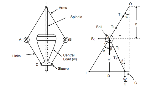
A schematic diagram of the porter governor is illustrated in Figure (a). There are two sets of arms. The top arms OA & OB associated balls to the hinge O. The hinge might be on the spindle or slightly away. The lower arms support dead weight and associate balls also. All of them rotate along the spindle. We may consider one-half of governors for equilibrium.
Assume w is the weight of the ball,
T1 and T2 are tension respectively in upper and lower arms,
Fc is the centrifugal force,
r is the radius of rotation of the ball from axis, and
I is the instant centre of the lower arm.
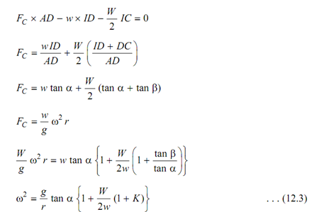
Taking moment of all of the forces acting on the ball and neglecting friction at the sleeve, we obtain following


(a) (b)
Porter Governor
If friction at the sleeve is f, the force at the sleeve must be replaced though W + f for increasing and by (W - f) for falling speed as friction apposes the motion of sleeve. Thus, if the friction at the sleeve is to be considered W must be replaced by (W ± f). The expression in equation (12.4) becomes
