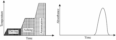
Heating cycle profile for graphite furnace:
The radiation from the line source is passed by the central hollow graphite tube holding the vaporised analyte. The absorption signal produced through this method is a transient one and lasts for a few seconds Figure (b). The signal will be acquired only while the analyte is atomised. You might note the correspondence among the atomization step and the analyte signal. This could be recorded on an appropriate chart recorder. This is in comparison with the flame atomisation technique whereas a steady absorption signal is acquired. Each graphite tube can be used for 100-200 analyses depending upon the nature of material.

(a) (b)
Figure: (a) A schematic heating cycle profile for graphite furnace (b) the transient absorption signal obtained by GAAFS
The sensitivity of GFAAS is much higher as compared to the flame AAS and the detection limits are lower through 2-3 orders of magnitude than which in flame AAS. This is so since within the furnace a much higher concentration of atomic vapour could be managed as compared along with flames. In addition, in this method, the dilution of the analyte through the solvent is prevented as the solvent is evapourated before the atomisation step.