Design of Four Bar Mechanism:
The relative pole may be utilized if length of the fixed link O2 O4, angular displacement θ12 (among position 1 & 2) of input link O2 A & angular displacement φ2 (among position 1 & 2) of follower link O4 B are known as.
(a) Find position of R12 as described in earlier section.
(b) The angle subtended through O2 O4 at R12 is ψ12 that is equivalent to
. Construct the similar angle at an arbitrary position. Join any two points on the two lines so obtained to achieve coupler AB of the mechanism. Join A along O2 and B having O4 to obtain the input link & follower link respectively.
(c) Situate point B arbitrarily so that O4B is the follower link. Build < B R12 Z equivalent to ψ12 Z. Choose an appropriate point A to R12 Z. Join AB and O2 A.
(d) Situate point A arbitrarily so that O2 A is input link. Build < A R12 Y = ψ12. Choose any point B on R12 Y. Join A & B to obtain AB. Join B with O4 to obtain follower link O4 B.
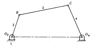
The four bar mechanism is illustrated in Figure.
