Tool Function
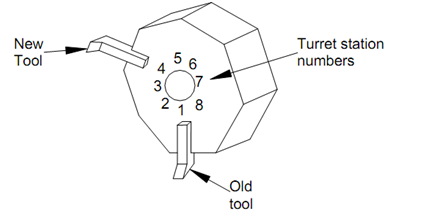
Tools are specified in a program using the T word address. Typically, the T word selects the turret station that is to be indexed to the cutting position and also activates the respective Tool offset register number. As shown in Figure 5.30, the turret positions are numbered which are used as the tool numbers. The T word has 4 digits, which are used as follows:
1. The first two digits are used as tool number.
2. The last two digits are used for the tool offset register number.

Figure 30: Indexing of the Tool Turret to bring the New Tool into Position
For example, T0104 means tool number 1 is to be associated with the tool offset register number 4. The tool number and the offset register number need not be same. In a given program, a single tool can be associated with more than one tool offset register. We will discuss this aspect at a little later to combine a number of rough machining cuts.
As the example in Figure 30 illustrates the current tool is positioned in pocket number 1. It is to be changed by the new tool located in the pocket number 4. The program may look like this :
N030 M06 T0103; (Bring tool 1 into cutting position)
-----
-----
N090 M06 T0406; (Bring tool 4 into cutting position)
The tool offset registers contain a number of values (Table 5.2), which are as follows:
- X and Z-axis tool offsets; used for generating the correct tool path from the programmed contour.
- Tool nose radius; used for compensating the tool nose radius.
- Tool nose orientation number; used for the correct application of the tool nose radius correction, which is explained later.
Table 2 : Contents of the Tool Offset Registers

It is necessary while programming to give all four digits in the tool word. If only two digits are programmed then the controller considers it as the offset register number and changes the values for the current tool in position.