Force Analysis in Worm Gears:
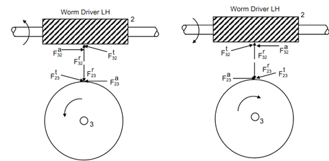
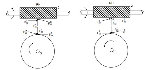
In worm and worm gear drive, worm is always the drive because this is a non-reversible drive. Worm might be left or right handed. The different kinds of components of normal tooth load on the worm have been illustrated in Figures 5(i), (ii), (iii) and (iv) for different sense of rotation and different hands.

(i) (ii)

(iii) (iv)
Figure 5 : Forces on Worm and Worm Gears
In Figures 5(i) and (ii) worm is left handed while in Figures 5(iii) and (iv) worm is right handed. For specified sense of rotation and hand the direction of components of normal tooth load is illustrated in Figure 5. The worm has been assumed as link 2 and worm gear is assumed as link 3. It might be observed that the tangential component in work produced a component parallel to the axis of the worm gear. The axial component in case of worm produced component in tangential direction in worm gear. For worm, lead angle (λ) is utilized in place of helix angle that is utilized for helical or spiral gears. Lead angle (λ) and helix angle (ψ) are related
ψ= (90o - λ)
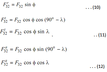
The radial component

Also

and
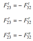
F23 = - F32
This might be observed that the radial component is directed towards the centre. The tangential component generated axial stress in the shaft of the worm gear. The axial component produced torque in the worm gear. The tangial component might be calculated for the worm by utilizing given speed, power & pitch circle radius. The normal tooth load then might be calculated by utilizing tangential component. Other quantities may be calculated afterwards by utilizing normal tooth load.