Estimate forces on the shaft:
A bevel gear train contains two gears. The pressure angle of the gear pair is 20o. The torque input to the gear 2 is as 8 kN cm. The gear train is illustrated in Figure 9. Estimate forces on the shaft at A & B, the bearings A & C take side thrusts.
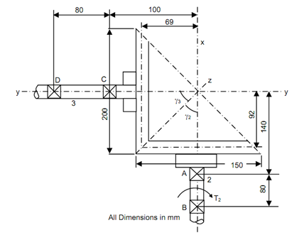
![2056_Estimate forces on the shaft.png](https://www.expertsmind.com/CMSImages/2056_Estimate%20forces%20on%20the%20shaft.png)
Figure 9
Solution
Torque input 'Ti' = 8 kN cm = 8000 N cm
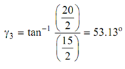
Pitch cone angle for the pinion
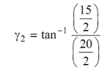
![1520_Estimate forces on the shaft1.png](https://www.expertsmind.com/CMSImages/1520_Estimate%20forces%20on%20the%20shaft1.png)
or γ2 = 36.87o
![2462_Estimate forces on the shaft2.png](https://www.expertsmind.com/CMSImages/2462_Estimate%20forces%20on%20the%20shaft2.png)
![1641_Estimate forces on the shaft3.png](https://www.expertsmind.com/CMSImages/1641_Estimate%20forces%20on%20the%20shaft3.png)
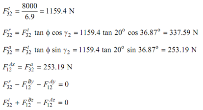
Taking moments around the Z-axis at point B
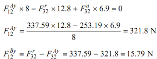
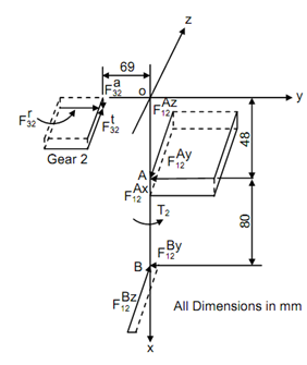
![479_Estimate forces on the shaft4.png](https://www.expertsmind.com/CMSImages/479_Estimate%20forces%20on%20the%20shaft4.png)
![425_Estimate forces on the shaft5.png](https://www.expertsmind.com/CMSImages/425_Estimate%20forces%20on%20the%20shaft5.png)
Figure 10
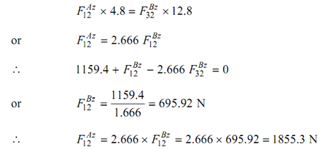
Taking moments around Y-axis passing through O
![2028_Estimate forces on the shaft6.png](https://www.expertsmind.com/CMSImages/2028_Estimate%20forces%20on%20the%20shaft6.png)
The components at the bearing A & B have been calculated. If obligation arises their resultant also may be calculated.