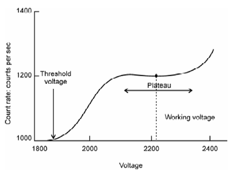
Illustration of plateau of a GM counter:
When the applied voltage is increased further, the electrostatic field becomes so large that a chain reaction results from the interaction of any ionizing particle, and proportionality between energy of radiation and the number of ion-pairs produced is lost. This does not happen all of a sudden in one instance. First this proportionality is lost gradually in the region between V3 and V4 and this part is called region of limited proportionality which is again of no use for the detection purposes. On further increase of voltage from V4 to V5, number of ion-pairs formed does not increase significantly. You may note that the region between V4 and V5 is independent of the type and energy of radiation. Beyond V5, discharge occurs throughout the volume of the detector making it totally ineffective and any approach to this region should be prevented. In this region, number of ion-pairs increase just slightly along with increasing voltage and is known as plateau. This is called the Geiger-Muller region and the detector operating in this region is referred to as GM counter. These counters generate huge voltage pulses and are simplest of all the detectors. Thus, GM counting systems are quite inexpensive compared to other detection systems. These counters are widely used for portable radiation monitoring and for counting gross activity in radiotracer experiments. The major limitation of a GM counter is their lack of energy discrimination. Also these are less efficient for x-and γ-ray measurements. A more general design of GM counter is the end window counter type frequent used for counting solid samples. The counter is cylindrical, made of stainless steel along with central hanging anode wire made of tungsten and a window made of aluminized mylar. The operating features of a GM counter are shown in Figure where count rate is plotted against applied voltage.

Figure: Illustration of plateau of a GM counter. Operating voltage is taken at the mid point plateau region
Working voltage corresponds to the midpoint of the plateau (somewhat plain region whereas number of ion pairs created does not vary significantly along with the voltage). Voltage at that the counter begins showing counts are known threshold voltage. In this plot, region beyond V5 is known discharge region and working in this voltage range is prohibited since it damages the GM tube.