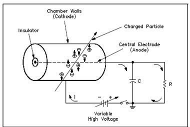
Schematic Diagram of a Gas-Filled Detector:
The pulsed operation of the gas-filled detector describes the principles of basic radiation detection. Gases are normally used in radiation detectors because their ionized particles could travel more freely than those of a liquid or a solid. Classical gases used in detectors are argon and helium, while boron-triflouride is utilized while the detector is to be used to measure neutrons. Below Figure displays a schematic diagram of a gas-filled chamber along with a central electrode.

Figure: Schematic Diagram of a Gas-Filled Detector
The central electrode, or anode, collects negative charges. An anode is insulated from the chamber walls and the cathode that collects positive charges. Voltage is applied to the anode and the chamber walls. A resistor in the circuit is shunted through a capacitor in parallel, so in which the anode is at a positive voltage along with respect to the detector wall. As a charged particle passes by the gas-filled chamber, it ionizes a few of the gas (air) along its path of travel. A positive anode attracts the electrons, or negative particles. The cathode, or detector wall, attracts the positive charges. A collection of these charges decreases the voltage across the capacitor, causing a pulse across the resistor which is recorded through an electronic circuit. The voltage applied to the anode and cathode determines the electric field and their strength.
As detector voltage is increased, the electric field has more influence upon electrons generated. Enough voltage causes a cascade effect which discharge more electrons from the cathode. Forces on the electron are greater and its mean-free path among collisions is decrease at this threshold. Calculating the modification in the capacitor's charge yields the height of the resulting pulse. Initial capacitor charge (Q), along with an applied voltage (V), and capacitance (C), is given through Equation 1.
Q = CV (1)
A change of charge (?Q) is proportional to the change in voltage (?V) and equals the height of the pulse, as given through Equation 6-5 or 6-6.
?Q = C?V (2)
?V = ?Q/ C (3)
The total number of electrons collected through the anode determines the change within the charge of the capacitor (?Q). A change in charge is directly associated to the total ionizing events that occur inside the gas. The ion pairs (n) initially formed through the incident radiation attains a great sufficient velocity to cause secondary ionization of other atoms or molecules in the gas. The resultant electrons cause additional ionizations. That multiplication of electrons is termed gas amplification. The gas amplification factor (A) designates the raise in ion pairs while the initial ion pairs create further ion pairs. Thus, the height of the pulse is provided through Equation 4.
?V = Ane/C (4)
where
?V = pulse height (volts)
A = gas amplification factor
n = initial ionizing events
e = charge of the electron (1.602 x 10⁻¹⁹ coulombs)
C = detector capacitance (farads)
The pulse height could be computed if the capacitance, detector features, and radiation are known. A capacitance is generally about 10-4 farads. The number of ionizing events might be calculated if the detector size and specific ionization and range of the charged particle is known. The only variable is the gas amplification factor which is dependent on applied voltage.