Vapor Absorption Refrigeration System
The figure shown below is the schematic diagram of simple vapor absorption refrigeration system (VARS). A cautious inspection of the figure exposes that the VARS system is necessarily similar as the simple VCRS; apart from that the compressor in the latter is substituted by the components within the dotted boundary in the schematic diagram of the former. Therefore, a VARS can be seen as a VCRS in which the compressor is substituted by the absorber – generator assembly. In VARS the work to be supplied for the liquid pump is unimportantly small as compared to the work needed by the compressor in a VCRS – a distinct benefit of the VARS. Though, a large quantity of heat needed to be supplied in the generator leads to bad performance of the VARS.
The VARS can therefore be used profitably and economically only in such situations where either waste heat is available as a by-product or low grade energy like solar energy is employed for providing cooling.
The working of the VARS is described shortly with the help of the schematic diagram shown below.
The working substance in the system is a refrigerant – absorbent solution. The refrigerant and absorbent chosen are such that the refrigerant is a low boiling point liquid and which has a high affinity to the absorbent.
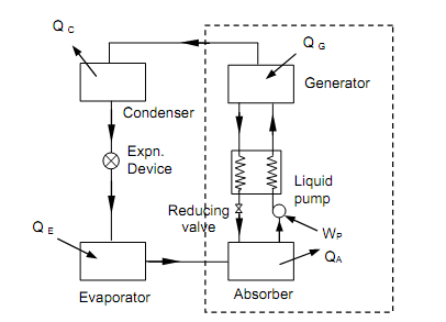
Figure: Vapor Absorption Refrigeration System
A strong refrigerant – absorbent solution is heated in the generator. Assume the heat transfer in the generator be QG. The refrigerant vapor leaving the generator at high pressure is condensed and cooled in the water cooled condenser. Assume QC be the heat transmitted from the refrigerant in the condenser. The liquid refrigerant from condenser is throttled via the expansion machine. Low quality refrigerant vapor entering the evaporator picks up heat (QE) from it to become saturated vapor and therefore generates the needed cooling as in the VCRS. The low pressure, low temperature vapor leaving the evaporator comes into the water cooled absorber where it meets the weak cool solution from the generator, the pressure difference among the generator and the absorber being sustained by the pressure reducing valve (i.e., the generator and condenser are on the high-pressure side of the system, whereas the evaporator and the absorber are on the low pressure side). The refrigerant vapor is absorbed by the feeble solution and the resultant strong solution is then pumped to the generator via the liquid to liquid heat exchanger. This heat exchanger is a significant component in the system. In heat exchanger, heat is transferred from the hot though weak solution coming from the generator to the strong solution going to the generator. Therefore, the heat exchanger makes sure that low temperature weak solution comes into the absorber to improve its performance, and high temperature strong solution comes into the generator to reduce the heat transfer in it, both contributing to the progress in performance of the system.
The COP of the system is provided by,
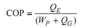
The COP is low since though WP is very small for a given QE, the QG needed is very large.
In the simple system described above it is supposed that pure refrigerant vapor leaves the generator to be condensed in the condenser. This is hardly a fact in practice. The vapor leaving the generator is rich only in the refrigerant component. It also brings a small fraction of absorbent. Such absorbent also acquires condensed in the condenser and whenever it enters the throttle valve gives increase to numerous problems in the expansion device and the evaporator. Therefore in the actual system provision should be made to remedy the vapor leaving the generator to make sure that only refrigerant vapor leaves the generator and the absorbent vapors are estranged, condensed and returned back to the generator. This is achieved by installing rectifying equipment (i.e., analyzer and a rectifier) on the generator.
Among the different refrigerant-absorbent combinations employed in VARS the most significant commercial combination has been the Ammonia-water mixture in which ammonia is the refrigerant. The VARS working with this mixture is termed as the Aqua-ammonia absorption refrigeration system.
The other popular mixture from the air-conditioning point is the water-Lithium Bromide mixture in which water is the refrigerant.