Reversed Brayton Cycle
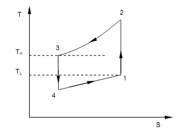
The figure shown below illustrates that the schematic diagram of the air cycle refrigeration system, the next figure shown below illustrates the cycle on which the system works. It is simple to comprehend from such figures that they are precisely similar, though for the directions of heat and work interactions. It is for this purpose that the ideal cycle on which air cycle refrigeration works is termed as the ‘reversed Joule or Brayton Cycle’.

Figure: Air Cycle Refrigeration System

Figure: Reversed Brayton Cycle
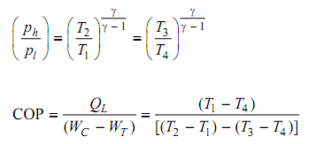
Air leaving the refrigerated space at state 1 is compressed to state 2 adiabatically and reversibly. The compressed air is then cooled at steady pressure, Ph, to state 3 by passing the air via the cooler. The air at state 3 is then extended adiabatically and reversibly in the turbine to state 4. The work yield of the turbine, WT, helps the compressor to the degree it can, therefore decreasing the total work to be supplied from outside from WC to (WC – WT). The low pressure, low temperature air at state 4 comes into the space to be refrigerated to pick up the heat to sustain the refrigerated space at a temperature corresponding to state 1.
Here, per kg air are the magnitudes of heat and work as follows,
QL = h1 – h4 = cp (t1 – t4)
WC = h2 – h1 = cp (t2 – t1)
QH = h2 – h3 = cp (t2 – t3)
WT = h3 – h4 = cp (t3 – t4)

Refrigeration capacity = m cp (T1 – T4)
Compressor power = m cp (T2 – T1)
The cycle above is only an ideal cycle and therefore the irreversibility in the compressor and turbine is not well thought-out. In real practice, since of irreversibility the temperatures at the end of compression and expansion rises, leading to reduce in COP of the system.