Part Programming Fundamentals
As discussed earlier, the numerical control machine tools require a part program to generate the requisite geometric shape of the components. The part program is basically a detailed step-by-step procedure that gives the necessary instructions to the various parts of a CNC machine tool, to produce the part. Thus, the actual utilization of the machine tool is as good as the part program that runs it. Hence it is a very important component in the use of CNC machine tools, to be able to write good part programs. In this unit, we will develop various elements that would help in writing the part programs for CNC machining centers.
To develop a part program, it is necessary to follow a series of steps in a proper sequence to come up with a satisfactory program. It is possible to make the same part by any number of procedures, but the one that uses the least amount of time and resources will be the best program. In order to achieve this, part programmer need to have sufficient amount of knowledge in a number of associated disciplines, such as machining and mathematics. The following are some of the steps that are detailed below:
The first step is to identify the various operations and surfaces that need to be machined in order to get the final shape of the part. This is termed as process planning. The process plan of a component in conventional machining consists of machine tool used, work holding fixtures required, and the sequence of operations. Additionally, for each of the operation, it is also necessary to identify the cutting tools required along with the process
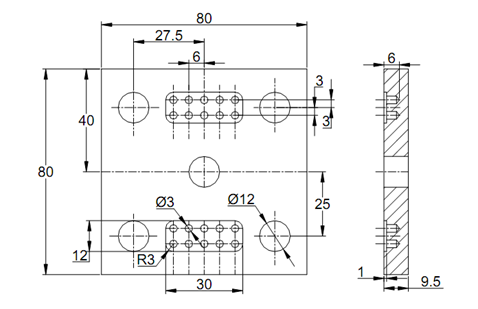
parameters such as cutting speed, depth of cut, and feed rate. A typical process plan is shown in Table for the part to be machined as shown in Figure 1.

Figure 1: A Typical Component for NC Machining
The next step involved will be the identification of the datum on the part that can be linked to the datum of the chosen CNC machine tool. The identification of the axes system of CNC machine tools is discussed in Unit 1. The part programmer will have to identify the datum and axes on the part in tune with that on the CNC machine tool. It is not necessary that the part datum and machine datum be the same, which is more difficult for operation. The CNC machine tools generally come with 'floating datum' whereby the part datum can be located anywhere in the machine tool's operation space.
Table 1 : Process Plan for the Component Shown in Figure 1

Care has to be taken in identifying the axes system, since the calculation of the coordinate values will be greatly affected by that choice. Generally there are two possibilities to locate the datum:
1. Lower left hand corner of the part as viewed in X-Y plane,
2. The geometric center of the part in case of a component geometry that is highly symmetrical.
Each of these has certain advantages in their own right.
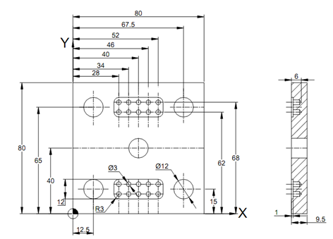
In the first case, when the datum is chosen as the lower left hand corner of the part as shown in Figure 2, you are keeping the entire part in the first quadrant of the coordinate system. This helps in the sense that all the dimensions would remain as positive, so less likely to make mistakes while entering the part program into the controller. At least in the initial stages, till the part programmer gains sufficient experience, it is desirable that he/she chooses this form of datum selection. Another advantage of this system is that the setting of the component on the machine tool table is readily done by touching the two edges.

Figure 2 : Same Part as in Figure 1 with Axes System at the Bottom Left Corner
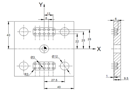
Alternatively the datum could be chosen as a point that is located at the geometric centre of the workpiece for symmetrical workpieces as shown in Figure 3. This helps in reducing the geometric calculations needed since you will be doing that only for one half or one quarter of the component and the rest could be manipulated by a simple sign change. Further, it would be possible to make use of the mirror facility in the controller to reduce size of the part program.

Figure 3: Part for NC Machining Shown with Axes System at the Geometric Centre for a Symmetrical Component
When it comes to the Z-axis datum, the option is relatively simple. It is generally kept to match with the top surface of the workpiece. This can be easily set as well as all the positive Z-motions will take the tool away from the workpiece, thereby avoiding any catastrophic collisions of the tool with workpiece in case of any errors in the part program.
After the datum selection, the next choice is that of cutting tools such that the most effective and economical tools are selected for the operation. Only the general purpose tools are used as far as possible, unless a required surface cannot be generated by them. Also the size of the tools has to be carefully selected from the geometry in question.
For a given tool and the operation selected, the suitable process parameters are to be selected. Generally these are to be taken from the handbooks supplied by the cutting tool manufacturers or based on the shop experience. Another aspect to remember is the planning of the various cuts, when large amount of material needs to be removed, for example in the case of cavity milling. This aspect is generally taken care of by the canned cycles, which will be discussed later.
The proving of a part program before that can actually cut metal is important. This is done in many ways. One of the simplest is the graphical proving of the part by software on the computer screen or on the MCU monitor.
After the graphical verification, a dry run on the machine tool may be carried out without a cutting tool to make sure that there are no unwanted motions present in the program. After a successful dry run, it would be possible to run the part program to make the part. If in doubt, the first component may be made in a soft material such as machinable wax, acrylic, nylon or Styrofoam. Having proven the part program, it can be released for production with appropriate documentation.